Ocpn_Draw 1.8
Developer: Jon Gough
Links
-
Releases: Github Releases
-
Download: Website Download
-
Forum: Ocpn_Draw Thread
Summary
The Ocpn_Draw Plugin (OD) is designed to allow users to place objects/items on the OpenCPN interface and have these georeferenced. This allows the objects/items to move with the chart and have a defined Latitude and Longitude. There are two basic types of object/item that can be used:
-
Points
-
Paths
Points are very similar to Waypoints and mark locations on the chart. Paths join two or more points together and draw a line between them. Currently these Points exist:
-
Boundary Point (BP)
-
Text Point (TP)
-
Electronic Bearing Line (EBL) Point
-
Dead Reckoning (DR) Point
-
Guard Zone (GZ) Point
These Points are used to construct special types of Paths:
-
Boundary (B)
-
Electronic Bearing Line (EBL)
-
Dead Reckoning (DR)
-
Guard Zone (GZ)
-
Parallel Index Line (PIL)
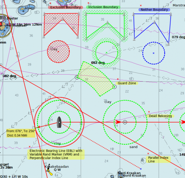
The example screen shot below shows an example of each type of Point and Path.
One user’s Feature Request:
“When Piloting the Range and Bearing of prominent bouys, chart features can be temporarily important as is the balance of the traffic. AIS proves the real time value of plotting these dynamic elements. Additionally, this point is reinforced where (Cursor) Range and Bearing is shown in places like the Dashboard or Status Bar. However, when piloting in unfamiliar waters it is useful to maintain an awareness of multiple landmarks. Much of the dead reckoning situational awareness in the absence of AIS targets is from Range and Bearing info, especially at night or in low visibility. A big benefit with respect to maintenance of situation awareness on deck. These range and bearing datapoints might be recorded/timestamped when arriving at designated DR waypoints as well. Range/Bearing Also, Useful when estimating arrival at a layline, given a known tacking angle and current heading”
His Comment after learning of ODraw:
“Thanks for the redirect. ODraw_PI works great for my purposes. We should definitely CLOSE this request….”
Integration with other plugins
There are two methods that plugins can use to interact with Ocpn_Draw_pi, the interactions are described for developers here: ODraw Messaging
WatchDog Alarms
Ocpn_Draw_pi (OD) provides a graphics companion to Watchdog_pi (WD) Alarms. OD is used as a graphics tool to create Boundary Graphics and Boundary Point Graphics. WD will then create “Boundary Alarms” using the Boundary Graphics created by OD. The alarms that WD can create are (GPS proximity, GPS course & time, Anchor, AIS) depending on the alarm type WD may require a particular Boundary GUID or the alarm may apply to all boundaries that are displayed. The WD alarm types are separate and distinct from the OD graphics types (inclusive, exclusive, neither). OD knows nothing about the WD plugin, it just responds with information about specific Lat/Lon combinations. WD can use the graphic type that OD has to help filter which boundaries to look for. So if you have a large number of boundaries of mixed 'types' it would probably help if you selected the type of boundary to look for rather than use the default 'Any'.
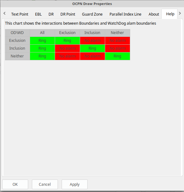
ODraw and WatchDog interactions
See the Development manual - Plugin Messaging - for messaging between ODraw , Watchdog and Weather_routing. A simple way to visualise the interactions between ODraw Boundaries and WatchDog boundaries alarms is laid out in this chart.
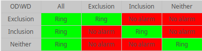
The chart shows which OD Boundary objects will cause a WD alarm to ring. If the WD alarm is set to Exclusion, the alarm will ring, go off, if an Exclusion boundary is found within the alarm area, i.e. time or distance. However, no other type of boundary will cause the alarm to go off. So when you setup the alarms you need to check the above matrix to ensure you will get the alarm when you want it.
You can set up multiple Dynamic Guard Zones and set the alarms for one, some or all of these zones.
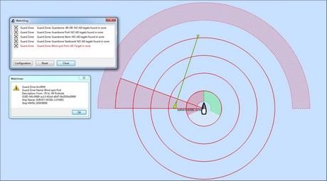
(Dynamic) Guard Zone Alarms are in some ways similar to the “AIS Collision Alarm” you can set in OpenCPN (Options-Ships-AIS Targets-CPA Calculation). But they are more versatile.
Weather routing integration
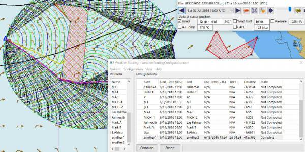
Red hatched Boundary created with Ocpn_Draw and used in Weather Routing Configuration > Options > Basic Tab > Check “Detect Boundary”
Squiddio integration
An extended API has been provisioned to allow other plugins to interact with the objects that OD supports. A new version of the Squiddio plugin is available which can make use of OD Text Points for the display of information. This removes the Squiddio waypoints from OCPN and replaces them with OD Text Points. This has the effect of decluttering the OCPN Routes and Waypoints Manager dialog. There is a new, extended, preferences dialog for Squiddio that allows the user to set various paramters for use with OD.
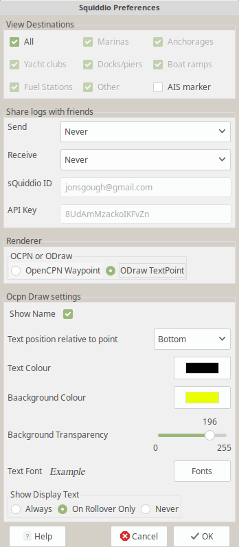
As can be seen it is easy to change between OCPN and OD for the display of Squiddio information. The extra information below the selection of which component to use is a subset of the settings available for Text Points. To find out more about Text Points please read further down on the manual.
Import Draw Objects
There are currently two different format files that allow importing of Draw objects, these are: gpx and csv. Examples of both formats can be found here: https://github.com/jongough/ocpn_draw_pi/tree/master/examples. Both of these formats allow you to generate Draw objects from other data sources and then import them rather than having to create each object then modify them to get the correct attributes.
GPX
The gpx format is an XML format file and is exactly the same as used by Draw for storing its objects over a restart. If you look in the 'ocpn_draw_pi/data' directory you will see one or more xml files these show all the attributes needed for creating a gpx file. Or if you want to generate your own gpx file then do an export of a single Draw object of the type you would like to import so that you have the complete structure which you can then modify and import. The following is an example (test export paths1.gpx):
<?xml version="1.0"?>
<OCPNDraw version="0.1" creator="OpenCPN" xmlns:xsi="http://www.w3.org/2001/XMLSchema-instance" xmlns:opencpn="http://www.opencpn.org">
  <opencpn:ODPoint lat="-22.966665000" lon="153.702456667">
    <opencpn:type>Boundary Point</opencpn:type>
    <time>2018-01-08T07:57:51Z</time>
    <opencpn:boundary_type>Exclusion</opencpn:boundary_type>
    <sym>Triangle</sym>
    <opencpn:guid>24ed5a17-c01e-477a-a51b-dfa3368b6ba0</opencpn:guid>
    <opencpn:viz>1</opencpn:viz>
    <opencpn:viz_name>0</opencpn:viz_name>
    <opencpn:arrival_radius>0.000</opencpn:arrival_radius>
    <opencpn:ODPoint_range_rings visible="false" number="0" step="1" units="0" colour="#FF0000" width="2" line_style="100" />
  </opencpn:ODPoint>
  <opencpn:ODPoint lat="-23.182036667" lon="153.635186667">
    <opencpn:type>Boundary Point</opencpn:type>
    <time>2018-01-08T07:57:52Z</time>
    <opencpn:boundary_type>Exclusion</opencpn:boundary_type>
    <sym>Triangle</sym>
    <opencpn:guid>4013a102-5ac4-47b0-a14a-bd2c3d3197be</opencpn:guid>
    <opencpn:viz>1</opencpn:viz>
    <opencpn:viz_name>0</opencpn:viz_name>
    <opencpn:arrival_radius>0.000</opencpn:arrival_radius>
    <opencpn:ODPoint_range_rings visible="false" number="0" step="1" units="0" colour="#FF0000" width="2" line_style="100" />
  </opencpn:ODPoint>
  <opencpn:ODPoint lat="-23.327897169" lon="153.454901890">
    <opencpn:type>Boundary Point</opencpn:type>
    <time>2018-01-08T07:57:53Z</time>
    <opencpn:boundary_type>Exclusion</opencpn:boundary_type>
    <sym>triangle</sym>
    <opencpn:guid>39b37b4d-568d-406d-8a18-214d467181f0</opencpn:guid>
    <opencpn:viz>1</opencpn:viz>
    <opencpn:viz_name>0</opencpn:viz_name>
    <opencpn:arrival_radius>0.000</opencpn:arrival_radius>
    <opencpn:ODPoint_range_rings visible="false" number="0" step="1" units="0" colour="#FF0000" width="2" line_style="100" />
  </opencpn:ODPoint>
  <opencpn:ODPoint lat="-23.295772262" lon="153.282689914">
    <opencpn:type>Boundary Point</opencpn:type>
    <time>2018-01-08T07:57:54Z</time>
    <opencpn:boundary_type>Exclusion</opencpn:boundary_type>
    <sym>triangle</sym>
    <opencpn:guid>24ea8aca-a730-4bb9-b3df-15db1267b19d</opencpn:guid>
    <opencpn:viz>1</opencpn:viz>
    <opencpn:viz_name>0</opencpn:viz_name>
    <opencpn:arrival_radius>0.000</opencpn:arrival_radius>
    <opencpn:ODPoint_range_rings visible="false" number="0" step="1" units="0" colour="#FF0000" width="2" line_style="100" />
  </opencpn:ODPoint>
</OCPNDraw>
CSV
The CSV format file is to allow you to use a spreadsheet program to easily generate objects. Here is an example (test-boundary-import.csv):
'c', 'type(B)','name', 'boundary_type', 'visible(t/f)', 'line rgb-colour', 'rgb-fill-colour'
'B','test boundary1','Exclusion','t','rgb(0,255,0)','rgb(255,0,0)'
'c', 'type(BP)', 'name', lat, lon, 'boundary_type', 'visible', 'rings-visible(t/f)', 'rings-number', 'rings-step', 'rings-units(N/K)', 'rings-colour'
'BP','first',-23.00,154.00
'BP','second',-23.5,154.00
'BP','third',-23.5,154.50
'BP','fourth',-23.0,154.50
'/B'
'B','test boundary2','Exclusion'
'BP','first',-22.00,154.00
'BP','second',-22.5,154.00
'BP','third',-22.5,154.50
'BP','fourth',-22.0,154.50
'/B'
'BP','isolated',-22.70,154.70
'c', 'type(TP)', 'name', lat, lon, 'position (t/ct/b/cb/c/r/l)', 'show (a/r/n)', 'visible (t/f)', 'display text'
'TP','my test text point',-22.70,154.70,'cb','a','t','this is one long line and should be treated as such. It is not designed to wrap'
'TP','my multiline text point',-22.90,154.70,'cb','a','t','this is not one long line\n and should not be treated as such.\nIt is designed to wrap'
The first label describes the type of line that follows, i.e. 'c' is a comment, 'B' is a Boundary, etc.
Using this format in a spreadsheet will allow you to easily create multiple Draw objects and then import them when you have finished.
Installation
This version of the plugin requires at least version of OpenCPN 5.xx.yy. It is not compatible with any version before this. The reason is that the user interface changed with OCPN 5 and a new graphics library was used. Download the plugin using OpenCPN Plugin Manager found in OpenCPN settings/Plugins.
Interface Icons
When OCPN_DRAW_PI is installed and activated you will see two new icons in the OpenCPN Toolbar, they will always appear together, but depending on the other plugins that are currently active may appear in different positions within the toolbar.
OCPNToolbar icons
The top icon is for the Draw Paths and Points Manger, the bottom icon is the Draw tool that was last used. This icon will change depening on the last tool used
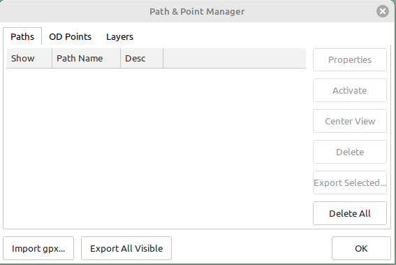
Draw Manager (top icon)
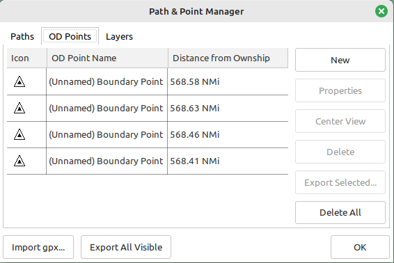
The top Icon is for the Draw Manager which gives the user control over each of the Drawing objects that have been created from the Draw Toolbar. Left click on the Drawing Manager menu and the Path & OD Point Manager dialog will be displayed. The Path & Point Manager has tabs for Paths, OD Points and Layers from which selected Drawing Objects can be Shown, Hidden, Deactivated, Centered, Deleted, Exported, Delete All, and Export All. Additionally a drawing object’s Properties can be accessed and changed. First select one or more Drawing Objects under a given Tab . Then select the desired Action on the right. For example: Select all Drawing Objects under Paths Tab , then select Delete . This will remove all of the Drawing Objects under Path Tab . Of course the quick alternative is to select Delete All . Properties, Deactivate and Center View are greyed out when more than one object is selected.
Draw Create (bottom icon)
The plugin has an interesting interface with two icons as shown above for Draw Manager and Draw Create . The bottom icon on the OCPN Toolbar, Draw Create, is dynamic and will show a different icon depending on which drawing object type has been selected. Click on the bottom icon on the OCPN Toolbar and a floating Draw Toolbar appears containing Draw Tools , with the last one used selected by default (appears depressed). Select the Drawing Tool needed. The above Draw Tools are for Boundary, then Boundary Points, Text points, EBL, DR, Guard Zone, and Parallel Index Line in that order. The Drawing Objects that are available are as follows:
-
 Boundary
 -
 Boundary points
 -
 Text points
 -
 Electronic Bearing Lines (EBL) & Variable Range Marker (VRM)
 -
 Dead Reckoning
 -
 Guard Zone (GZ)
 -
 Parallel Index Line (PIL)
Draw Toolbar
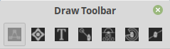
Depending on the settings you have chosen for Draw this toolbar may never be displayed, displayed whilst a drawing tool is in use or always displayed. There are 7 icons to choose between and each activates a different tool. The currently active tool icon will also show in the OCPN Toolbar when you are drawing. If you have finished drawing the last active tool is shown in the OCPN Toolbar for easy, quick, access to the last tool.
Try drawing several of each type to learn how they work and what they create. You can select the next tool in sequence by right clicking the mouse prior to starting to draw. Once a left mouse click has been done the right click will terminate the 'create' drawing. You can also stop the 'create' mode by hitting 'Esc', left mouse clicking the selected tool in the main toolbar or by left mouse clicking on the close icon in the 'Draw Toolbar'. It sounds complicated, but you will find one of the methods should meet your normal usage requirements.
Each tool has a cursor icon:
-
Boundary: Pencil
-
Boundary Point: Red Cross
-
Text Point: 'I' icon
-
EBL: Red Cross and a line joining the cursor to the boat
-
DR: Red Cross
-
GZ: Pencil
-
PIL: Red Cross
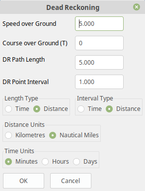
The DR tool does not draw based on the current cursor position, it brings up a dialog box that allows you to enter the DR information.
When you left mouse click 'OK' the DR line will be drawn based on the information you have entered. The information that is first displayed is the default information entered into the properties panel or the current information available to OpenCPN, i.e. SOG and COG.
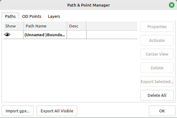
Draw Manager 
Clicking on this icon will open the Draw Manager dialog box. This will allow you to interact with any of the Draw objects that have been drawn in the current session, including those that were loaded from the last OpenCPN session.
There are three tabs, Paths, OD Points and Layers. Paths is the generic name for objects that have drawn lines, OD Points and the points on the display between which the lines are drawn and Layers are a waypoint of collecting Draw objects into groups that can be displayed or hidden by a single action.
Eample pages:
Paths
OD Points
Layers
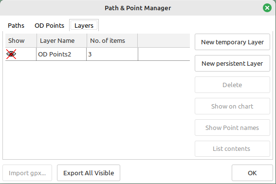
Layers
Drawing Objects imported into Layers are static and non editable. Use Layers in the same way as the OCPN Route and Waypoint manager does, i.e. Temporary Layers. It will bring in boundaries and points and show or hide them as required. You can load more than one layer file into the same layer, just select more than one file in the file manager popup and they will load into the same layer. To use Layers and move Drawing Objects into a temporary user created Layer, select them, Export Selected and then import then from the Layers tab Import.
Layers can also be persistent meaning that the layer will be reloaded after a restart. By default persistent layers will not be shown, however, this behaviour can be changed by setting the either Show Layers checkbox or Remember layer visibility over restart checkbox to a tick. Show Layers will show all layers loaded. Remember layer visibility over restart will show layers shown at last restart.
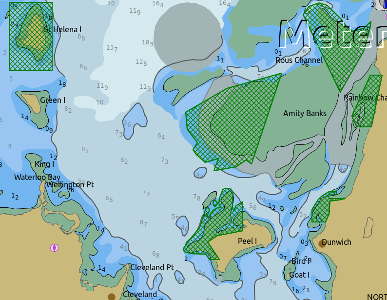
An OpenCPN user has provided a set of layers for use within Draw describing zoning in Queensland Great Barrier Reef Marine Park (GBRMP), the Great Sandy Marine Park (GSMP) and the Moreton _Boundary Marine Park (MBMP). These show the usage allowed in each zone and the limits of such zones. These can be found here: https://github.com/redog666/qld-coastal-zones The following is an excerpt from the Moreton Bay area:
Edit Mode for Draw Objects
First, if you are in the 'create' mode you must terminate this by, Right
Click of mouse, button, Left Click on the tool you are using or hit
'Esc' on the keyboard. Then in the drawing hover over the object you
wish to modify until a square yellow descriptor appears, then right
click. The popup menu’s first line will identify the type of drawing
object you have selected. Then there will be a action pick list,
dependent on the object, such as Properties, Move.., Insert..
Deactivate.. Delete. Some drawing objects are made of several parts,
(Boundary, Boundary Points, EBL & VRM, GZ and PIL) so it makes a
difference where you hover and the condition of the object.
1. To select a Boundary, hover over the edges. To select a boundary
point hover over it.
2. To select an EBL hover over the ends or the shaft, depending on
whether the EBL is centered on a boat or lat/long the right click
actions will be different. The popup menu list selections should be self
explanatory.
When you have right clicked and selected an action, for example to move a boundary, text point or boundary point, the point will be highlighted with a yellow dot. Complete the move by dragging and releasing. For editing any characteristics such as color, line thickness, font, etc, use 'Properties', but if you just want to move a point select 'Move'. To move a point you will need to right click and select move. Having selected move you will then need to put the cursor over the selected object, push and hold the left mouse button and drag the object to where you want it. When you let go of the left mouse button the cursor (what ever it was showing before) should revert to the standard pointer and the 'move' process is terminated. If you want to move the object again, you will have to right click again to get the popup and repeat the process.
Draw Object Properties
There are multiple ways to access an object’s Properties .
-
In Path & Point Manager double click on a Drawing Object, Properties will appear.
-
In the Drawing hover over the Drawing Object, right click and pick Properties .
-
In the Drawing hover over the Drawing Object, double left click, Properties will appear.
It is also possible to drill down into an object if it is multi-part, i.e. get a Boundary properties dialog displayed then right click or double click any line showing a Boundary point and the properties for that point will be displayed.
Constrained moves
When moving an object you can move it in any direction just by holding the left hand mouse button down and dragging. If you want to constrain the movement to horizontal or vertical you need to use the Ctrl key to only allow vertical movement or the Shift key to only allow horizontal movement. If you release the key whilst dragging the constraint is removed. You can press and hold one of the two keys at any time during the movement, the constraint only applies when the key is held down. Additionally, when used with EBL pressing Ctrl + Shift at the same time, will constrain the angle value and allow movement along the angle. This will also work when perpendicular line is checked.
Whole Boundary moves
A boundary can be moved as a single object or a single line of the boundary can be moved. The default action is to move the whole boundary, but you can select 'Move Boundary Segment' from the right mouse button popup menu.
Boundary merges
If you have two or more boundaries you can select these and merge the boundaries together. This is accomplished by hold the Ctrl key down then left mouse clicking on the boundaries you want to merge. Each boundary selected will flicker showing it has been selected. If you then right click on a boundary you will be presented with a merge popup. This will allow you to merge and keep the current boundaries, this draws a bounding boundary around the selected boundaries. If you select merge and delete you will draw a bounding box around the boundaries then the original boundaries will be deleted. There is no undo, so care needs to be taken.
Available Drawing tools
This section will describe in more detail the drawing tools that are available with this Plug In.
Boundary
This allows drawing of a closed path joining all points that of the path. The smallest Boundary has two points, but normal Boundaries will have three (triangle) or more points. There is no limit to the number of points, or the size of the Boundary. When drawing points that have already been placed will be connected togther with the path line. A rubber band line will be drawn that follows the cursor. The boundary fill may appear incomplete or strange at this point. However, when the final point is place and the create process is finished it will correct itself and display the boundary fill correctly.
If a point is placed in the wrong location carry on laying the other points. When you have finished the create process you can then edit the boundary and 'Move', 'Delete' or 'Add' more points to the boundary. If the whole boundary is in the wrong location it can be moved as a whole from the right mouse click menu.
The types of boundary you can draw, which can be easily changed after creation if it is wrong, are:
-
Exclusion - The interior of the boundary will have a cross hatch pattern of the selected color. The type of boundary reported to other plugins, such as Watchdog, will be of type 'Exclusion'.
-
Inclusion - A user defined width cross hatch pattern will be drawn around the outside of the boundary in the selected color. The type of boundary reported to other plugins, such as Watchdog, will be of type 'Inclusion'.
-
Neither - The boundary will be drawn as a line with no interior or exterior fill. The type of boundary reported to other plugins, such as Watchdog, will be of type 'Neither'.
Please Note that these Types (exclusion, inclusion, neither) are Graphical only, and WatchDog does not use them in setting its internal alarms. We recommend that these graphic types be used appropriately to conform with the type of alarm that will be set from within WatchDog, however they will have NO EFFECT on the WD alarm type.
The type of boundary may change what other plugins do with the information, or how it is displayed. If using the Watchdog plugin and you set the boundary anchor watch the alarm will go off if you move outside of the boundary. If you are motoring/sailing and you have a proximity boundary watch set then the alarm will go off if you get closer than the specified distance. The first type of boundary should be an 'Inclusion' boundary and the second should be an 'Exclusion' boundary.
Note: A Boundary is a line joining two or more Boundary Points together. As such, each Boundary Point can have the same capabilities as individual Boundary Points.
Boundary Point
This allows the placing of individual points on the chart. They are very similar to 'Marks' that can be dropped by OpenCPN. However, they have the capability of being 'Exclusion', 'Inclusion' and 'Neither' boundary points. This is demonstrated when Range Rings are Displayed.
-
Exclusion - The interior of the boundary point, from the biggest range ring, will have a cross hatch pattern of the selected color. The type of boundary point reported to other plugins, such as Watchdog, will be of type 'Exclusion'.
-
Inclusion - A user defined width cross hatch pattern will be drawn around the outside of the largest range ring of the boundary point in the selected color. The type of boundary point reported to other plugins, such as Watchdog, will be of type 'Inclusion'.
-
Neither - The boundary range rings will be drawn as a line with no interior or exterior fill. The type of boundary point reported to other plugins, such as Watchdog, will be of type 'Neither'.
Please Note that these Types (exclusion, inclusion, neither) are Graphical only, and WatchDog does not use them in setting its internal alarms. We recommend that these graphic types be used appropriately to conform with the type of alarm that will be set from within WatchDog, however they will have NO EFFECT on the WD alarm type.
Boundary Points continue to be placed on the chart until the drawing create mode is terminated. This allows the placing of as many points with single mouse left clicks as the user wishes.
Text Point
This allows the placing of individual Text Points on the chart. They appear very similar to Boundary Points, but they allow the displaying of multi-line text in the desired font. They can have range rings, but these cannot be filled.
The text top left corner of the text is the reference point. There are 7 provided locations:
-
Top - which puts the text over the top of the point aligned to the left edge of the icon with the bottom just clear of the icon
-
Top center - which puts the text over the top of the point with the center of the text aligned to the center of the icon
-
Bottom - which puts the top edge just underneath the point aligned to the left edge of the icon. If you displace the point name the text should drop enough to show it
-
Bottom center - which puts the text underneath the point with the center of the text aligned to the center of the icon
-
center - which puts the text horizontal and vertical center over the icon.
-
Right - which puts the top edge aligned with the top of the icon, the left hand edge of the text just clear of the right hand side of the icon
-
Left - which puts the top edge aligned with the top of the icon, the text to the left of the icon with the right hand end of the text box just clear of the icon
The amount the box edge is offset is controlled by 8 settings in the opencpn ini/conf file. You will find them called:
-
DefaultTextTopOffsetX
-
DefaultTextTopOffsetY
-
DefaultTextBottomOffsetX
-
DefaultTextBottomOffsetY
-
DefaultTextRightOffsetX
-
DefaultTextRightOffsetY
-
DefaultTextLeftOffsetX
-
DefaultTextLeftOffsetY
These are not in any dialog box as they are very unlikely to be modified.
Changing the font in the properties box does not apply the font until the OK button is pressed on the properties box. The word 'Example' should change to show you the font selected. Changing the font in the properties box does not apply the font until the OK button is pressed on the properties box. The word 'Example' should change to show you the font selected.
When a Text Point is created the 'natural' scale at which it is created is stored. This is then used to determine what to show when scaling to larger scales. Currently at twice the natural scale the text gets hidden and at 8x the natural scale the text box gets hidden. This is currently hard coded.
To display text for the Text Point you will need to open the properties for the Text Point and fill in the 'Display Text' tab. This is simple text and does not allow individual formatting of different parts of the text. You can pick the font and the font metrics to use for all the text associated with one text point.
Electronic Bearing Line (EBL)
The EBL always starts attached to the boat with the far end of the line being placed by left clicking the chart. The default action for the end point is set in the main properties dialog. The end point can either be fixed to a Latitude and Longitude or move along with the boat. This allows the EBL to show the boat moving against a fixed point, i.e. passing a reef, or to show other objects moving relative to the boat, i.e. when the boat can tack to get around a bouy.
The EBL can be detached from the boat to allow placing of the start point where the user left clicks. The EBL can also then have the start point centerd on the boat but not move or re-attached to the boat.
Variable Range Markers (VRM’s) can be displayed as part of the EBL, by checking a box on the EBL properties (or set the default on the OD properties) and a range ring will be drawn based on the start point. If the end point of the EBL is moved the range ring will move with that point. This allows easily setting up of safety rings around a boat. The plugin provides additional information when moving the end point of an EBL/VRM
End Points A & B of an EBL can be in several states:
1. Associated with Boat position (boat lat long) - Moving with the
boat.
2. Associated with a fixed position (lat long) - Not Moving with the
boat.
3. When offset Point B is associated with Boat position (lat long) it
moves relative to the boat position and stays at the same angle.
Right click selections for EBL are
1. When the EBL start point is attached to the boat… Pick a new start
point.
2. When the EBL start point is not on the boat.. Center on moving boat
or Center on Lat/Lon (not fixed to the boat)
This flexibilty is useful for Dead Reckoning to have “Fixed” EBL markers.
The default color is the same as for a 'Boundary Point' and it will draw 1 range ring. If you want to change that then you will need to get to the start point properties (double click the EBL and double click the first point), or if the first point is clearly visible, just go to its properties (right click the point and select properties) and you can change the number of rings, the colors. The rings cannot be filled.
The VRM colour, by default is set to the same as the default for a Boundary Point, but once you change the VRM color to be different from the Boundary Point default then it will stay this way, unless you select the match option in the right click menu.
There are two ways of changing the VRM color:
-
Under properties for the EBL with the VRM showing. Change the EBL color and the VRM color will also change.
-
Under properties for the EBL with the VRM showing get the properties of the 'boat'/'start' point and change the color.
It may seem strange at first to use an EBL to give you the VRM, but it makes selecting the VRM easier so that it can be dragged to the size required as there is a well defined point that can be selected. This is particularly true if you have many VRM’s at one time.
It is not necessary to loop through the preferences to enable the VRM for one EBL–the settings pop-up double clicking the EBL has all the necessary entries.
The popup for EBL’s contains both the forward and back bearing.
The main properties dialog in the general tab sets whether to use magnetic bearings or true. If magnetic is used then if you have the World Magnetic Model installed the variation will be used from that plugin. If not you will, currently, need to set 'UserMagVariation=0.00' in the ocpn_draw_pi section of the config file as there is no setting in the properties dialog for this.
Dead Reckoning (DR)
This draws a Dead Reckoning line with multiple points along it starting at the boats current location. As mentioned above, this tool does not use the mouse click to draw on the chart, rather it uses it to display a dialog box where the DR information can be entered. When the 'OK' button is clicked the DR will be created and drawn on the chart. At this point the line can be modified by changing the points that make it up. However, this may make the DR line not reflect what you expect as neither the time/distance between points is maintained, nor is the COG/SOG. So the DR line at that point becomes more of a line with possibly little meaning in the context of DR.
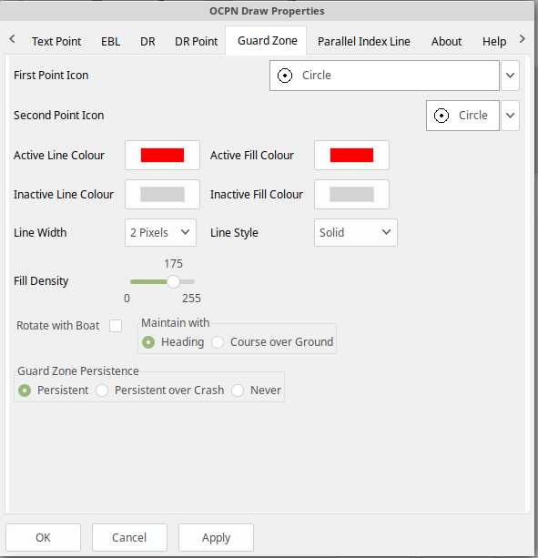
Guard Zone (GZ)
This draws a segment of a torus or doughnut. The centre is the boat and the angle and size is determined from the two points that are used to describe the GZ. When the GZ tool is selected the cursor will change to a pencil and a line will join it to the centre of the boat. When the left mouse button is clicked the first point of the GZ is dropped. Now when the mouse pointer is moved an angular segment of a torus is drawn, the size of which is determined based on where the mouse cursor is. The second point is dropped when the left mouse button is clicked. This completes the drawing of the GZ which will now be the default colour and filled in with a hatch of the default colour.
The GZ can rotate with the boat and be maintained with the heading or the coarse over ground. Or it can maintain its position relative to the boat irrespective of which direction the boat is moving. This is set in the default propertiesd but can also be changed for each individual GZ.
Parallel Index Line (PIL)
Annex to IMO res.A893(21)-Guidelines For Voyage Planning. Section 4- Appraisal
-
“Additional information which should be marked on the charts include: ….. Parallel index lines should also be drawn where appropriate.”
Annex to IMO res.A893(21)-Guidelines For Voyage Planning. Section 6- Monitoring, point (j)
-
“Radar can be used to advantage in monitoring the position of the vessel by the use of parallel indexing, which is a simple and most effective way of continuously monitoring that a vessel is maintaining its track in restricted coastal waters. Parallel indexing can be used in any situation where a radar-conspicuous navigation mark is available and it is practicable to monitor continuously the vessel’s position relative to such an object. It also serves as a valuable check on the vessel’s progress when using an electronic chart.”
This allows drawing a line which offset from a centre line by a specified amount. This offset line will move with the boat and can either rotate with the boat or stay at a specified angle. Drawing a PIL is the same as drawing an EBL. The index line only shows up when the centre line has been drawn.
Each PIL centre line can have multiple offset lines. To create more than the first line right click the centre PIL line and select 'Add Index Line'. A new index line will be drawn based on the default settings.
End Points A & B of an PIL can be in several states:
1. Associated with Boat position (boat lat long) - Moving with the
boat.
2. Associated with a fixed position (lat long) - Not Moving with the
boat.
3. When offset Point B is associated with Boat position (lat long) it
moves relative to the boat position and stays at the same angle.
Right click selections for PILL are
1. When the EBL start point is attached to the boat… Pick a new start
point.
2. When the EBL start point is not on the boat.. Center on moving boat
or Center on Lat/Lon (not fixed to the boat)
The offset line has its own properties box which can be accessed by either right clicking the offset line or by double left clicking the offset line.
Each offset line can be moved using either left drag (if enabled) or right clicking the line and selecting move.
How to use PIL Good Parallel Index Line video link
How to plot for Collision Avoidance Collision Avoidance Plotting Part1 of 3
Properties dialogs
All objects that have been drawn have a properties dialog associated with them to allow changing of the objects attributes.
Boundary Properties
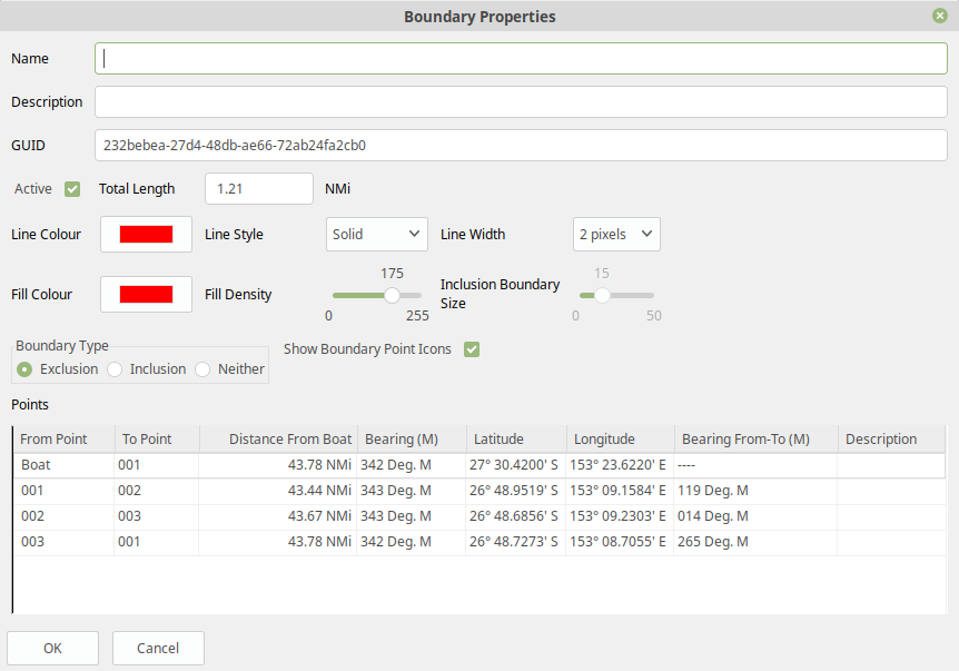
You can display the point properties by either double left mouse clicking on the particular line you want in the Points list or by right mouse clicking on the line, once it has been selected, and selecting 'Boundary Point Properties' from the popup menu. If you want to remove a particular point then left click the line to select it. Then right mouse click on the point and select 'Remove Selected' from the popup menu.
Basic
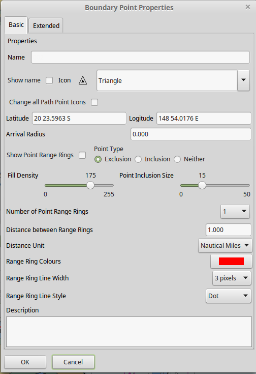
These are the properties for the selected Boundary Point. Any changes here will be made to the selected Boundary Point and, if the 'OK' button is clicked, will be preserved over a restart.
Extended
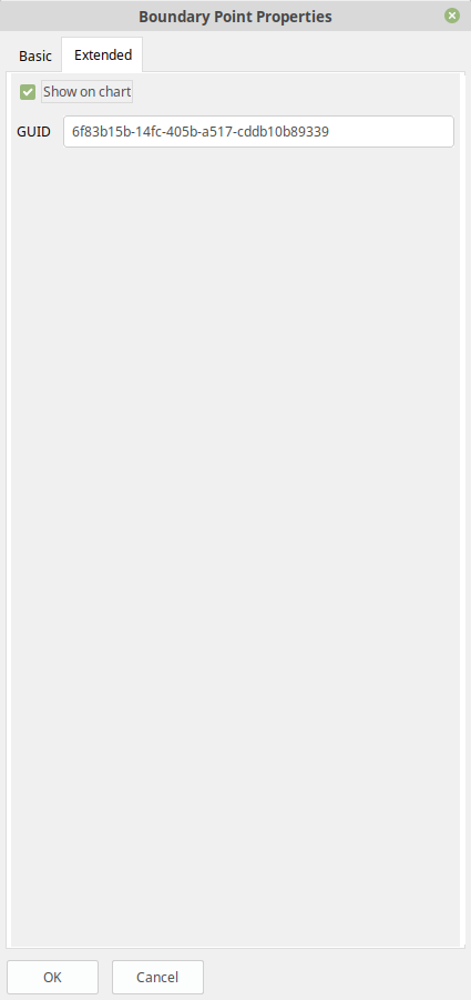
This allows you to stop displaying the Boundary Point on the screen and change the GUID if you want. You will need to click 'OK' to save the changes.
Basic
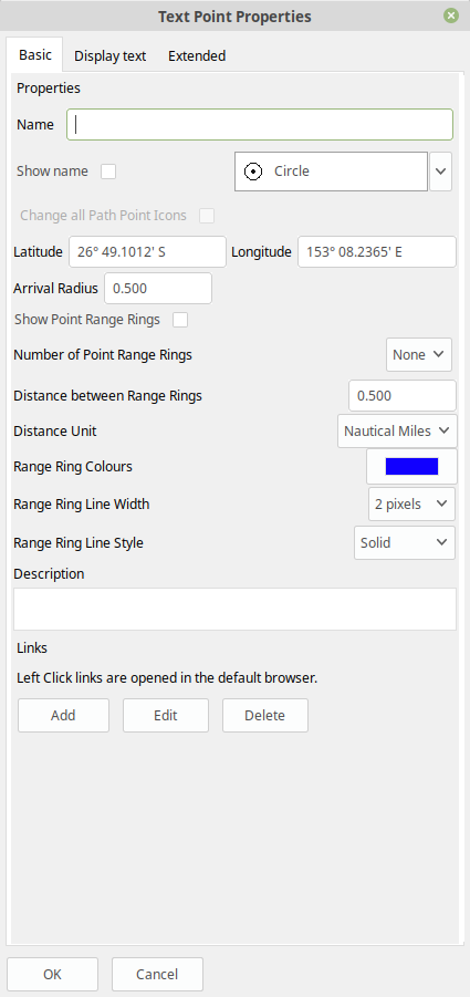
This tab controls the text that is displayed for the Text Point. Any changes here will be made to the selected Text Point and, if the 'OK' button is clicked, will be preserved over a restart.
Display Text
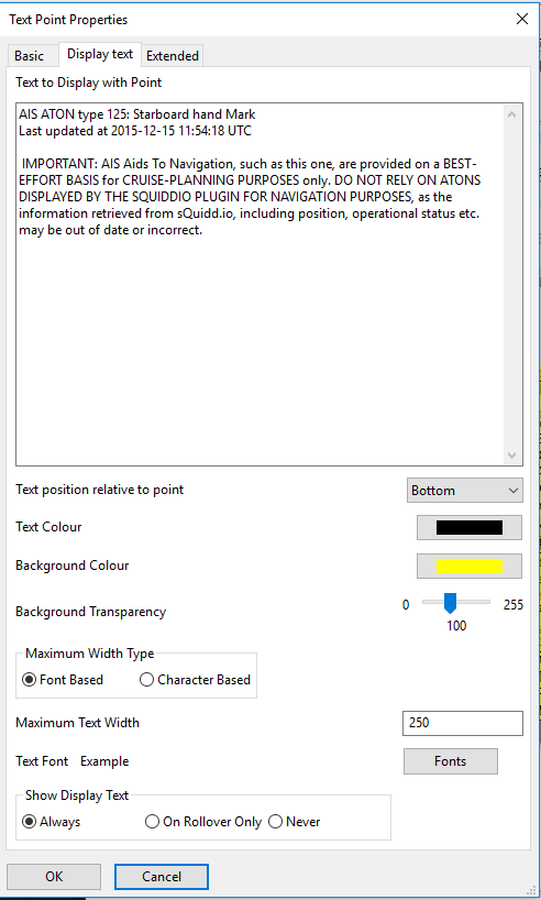
This tab is used to create and modify the text that will be displayed with the Text Point. It also allows the setting of values for an individual Text Point where as in the Preferences you settup the system wide settings.
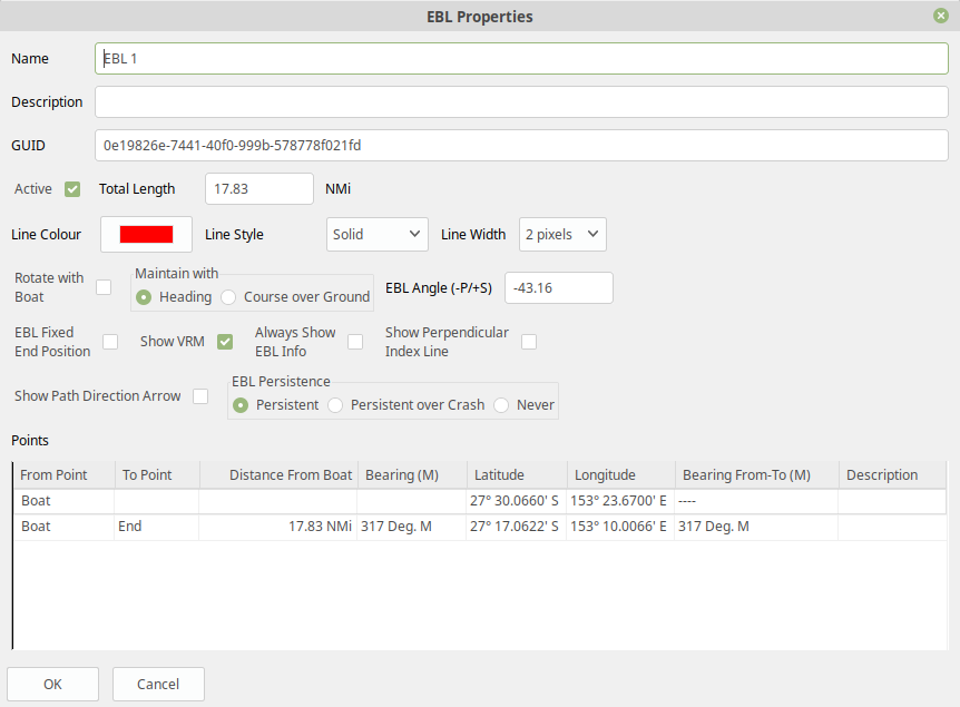
Basic
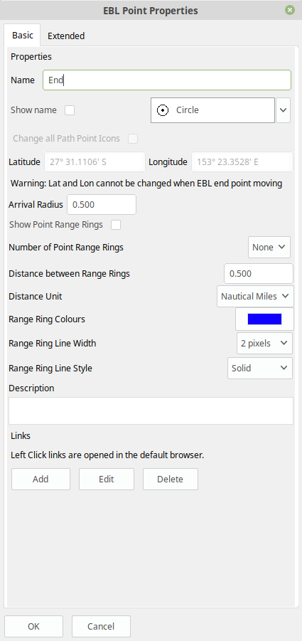
These are the properties for the selected EBL Point. Any changes here will be made to the selected EBL Point and, if the 'OK' button is clicked, will be preserved over a restart.
Basic
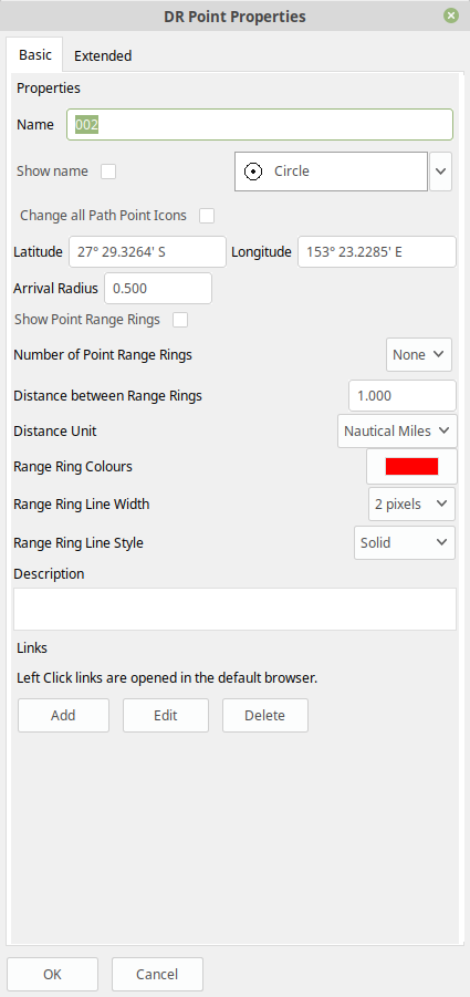
These are the properties for the selected DR Point. Any changes here will be made to the selected DR Point and, if the 'OK' button is clicked, will be preserved over a restart.
Other
Copy and paste Lat/lon point
In any of the 'Point' property dialogs you can right click in either the Lat or Lon and get a drop down menu where you can select:
-
Copy
-
Copy Lat/Lon
-
Paste
-
Paste Lat/Lon
These will either copy/past in the selected box or will copy/paste both the Latitude and Longitude at the same time.
Settings

Options > Plugins > Ocpn Draw > Preferences
Under Preferences the Tabs are General, Boundary, Boundary Point, Text
Point, Path, EBL, DR, DR Point, Guard Zone, Parallel Index Line, About
and Help where various settings are selected. Generally the defaults
should give a reasonable starting point. However, all the defaults that
are used can be changed from here.
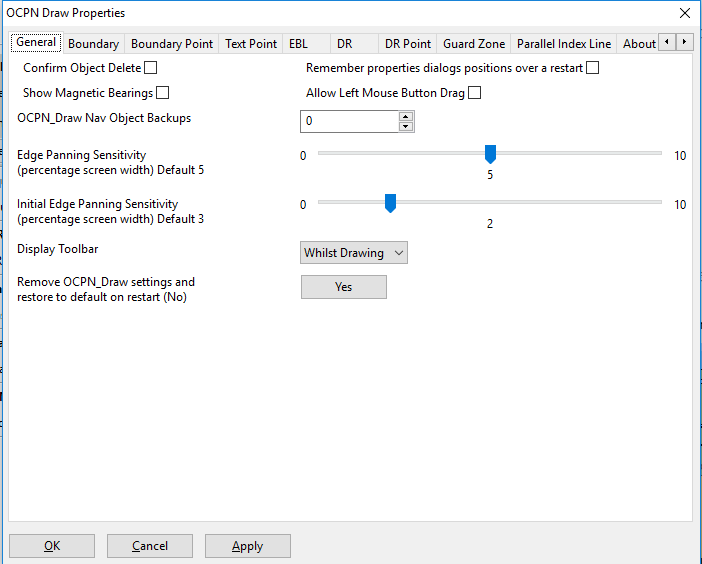
Confirm Object Delete
This setting determines whether a dialog box will be shown asking for conformation about deleting any objects. With it checked you will be asked to confirm all deletes, with it unchecked you will be able to delete any object without being asked for confirmation. If you do delete an object by mistake and you have 'Nav Object Backups' set to more than 0, you will be able to use one of those backups to restore your objects.
Remember properties dialog positions over restart
This setting saves the position of each dialog over a restart. If the user moves a dialog it will be in the same position when it is displayed after a restart. If this setting is not checked the default position, centre of the OCPN screen, will be used when the dialog is first displayed after a restart
Show Magnetic Bearings
If this is checked and there is a magnetic variation available then this will be applied to all angles that are used within the plugin. If it is checked and there is no magnetic variation available it will assume a '0' variation.
Allow Left Mouse Button Drag
This setting allows dragging objects by placing the mouse over the object, pressing and holding the left mouse button and dragging the object to the desired location.
If this setting is off you will need to right click on the object to get the popup menu and select move from that. Then you can press and hold the left mouse button and drag the object.
A word of warning from user Redog: If “Allow Left Mouse Button Drag” is checked it is very easy to move your entire boundary or zone to a new location, thus changing all coordinates of waypoints you may have painstakingly entered. If you only intend to move 1 waypoint leave unchecked and use right click and move waypoint. If you intend to move entire zone check this option, it is a brilliant concept and very useful.
Show Layers
This checkbox hides, unchecked, or shows, checked, layers on restart. If this checkbox is checked it disables the Remember layer visibility over restart checkbox.
Remember layer visibility over restart
This checkbox causes the currently displayed layers to be displayed again over a restart of OpenCPN. If this checkbox is checked it disables the Show Layers checkbox.
Nav Object Backups
This setting determines how many backups to keep of the navigation objects file. The location of the files can be found in the opencpn.log file. Each time OpenCPN stops a new copy of the navigation obj file will be created. The latest file is called 'ODnavobj.xml'.
Edge Panning Sensitivity
This is the percentage of the screen size distance from the edge that will cause the screen to pan when using the drawing tools. The bigger this number the further from the edge of the screen your pointer will be when the screen starts panning.
Initial Edge Panning Sensitivity
This is the same as above, but is used after a drawing tool is picked but before the first object is created. This is supplied so that the screen does not start panning if you move your pointer off of the toll bar near the edge of the screen.
Toolbar icon scaling (requires restart)
If the OCPN Draw toolbar is not the required size this item allows scaling of the icons. On most systems this will require restarting OpenCPN, or deactivating and reactivating OCPN Draw.
Display Toolbar
The plugin allows you to use two graphical methods of selecting the tool you wish to draw with:
-
The main Toolbar and the right mouse click
-
The Draw Toolbar
This setting determines if the tool bar is display and has three settings
-
Never - the toolbar is not displayed
-
Whilst Drawing - the toolbar is displayed whilst a drawing tool is active
-
Always - the toolbar will display all the time irrerspective of whether you are using the plugin.
Remove OCPN_Draw settings and restore to default on restart(No)
This setting allows the user to set all settings back to the default value. If the button has the label 'Yes' and it is clicked this will ensure that no OCPN Draw settings are saved when OCPN is shut down. The text of the label will be changed to 'Remove OCPN_Draw setting and restore to default on restart (Yes)' to indicate what will happen. The button label will now say 'No' indicating what will hapen if it is clicked again.
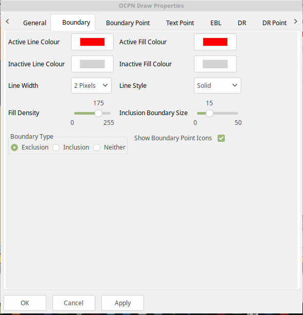
Active Line Color
This is the color of an active Boundary Line
Selection is by a platform specific color picker. This will allow the
color to be any RGB (Red, Green, Blue) color that is supported by the
platform.
Active Fill Color
This is the default color to use for any active Boundary fill hash. When selected a standard, platform dependent, color picker will be presented. This will allow the color to be any RGB (Red, Green, Blue) color that is supported by the platform.
Inactive Line Color
This is the color of an inactive Boundary Line.
Selection is by a platform specific color picker. This will allow the
color to be any RGB (Red, Green, Blue) color that is supported by the
platform.
Inactive Fill Color
This is the default color to use for any inactive Boundary fill hash. When selected a standard, platform dependent, color picker will be presented. This will allow the color to be any RGB (Red, Green, Blue) color that is supported by the platform.
Line Width
This is the width of the Boundary Line in pixels. It can be a value between 1 and 10 pixels.
Line Style
This defines how the Boundary Line is drawn. It can be one of the following:
-
Solid
-
Dot
-
Long Dash
-
Short Dash
-
Dot Dash
Some of these may not display well on your screen depending on the resolution you are using. It is known that when using high resolution screens, i.e. 3800×1900 the difference between the line types may be difficult to see.
Fill Density
This allows the setting of how transparent the fill hash is. A value of 0 means that it is fully transparent and a value of 255 is that it is fully opaque. The term density is used as it seemed clearer, i.e. low density - you can see through it, high density - you cannot see through it.
Inclusion Boundary Size
This defines, in pixels, how wide the hash is around the outside Boundary Line when the Boundary is of type 'Inclusion'.
Boundary Type
This radio button selection sets the default type for all Boundary. Points.
-
Exclusion - fill the inside of the Boundary with a hash.
-
Inclusion - surround the Boundary with a nominated size hash
-
Neither - just draw the Boundary Line with no hash
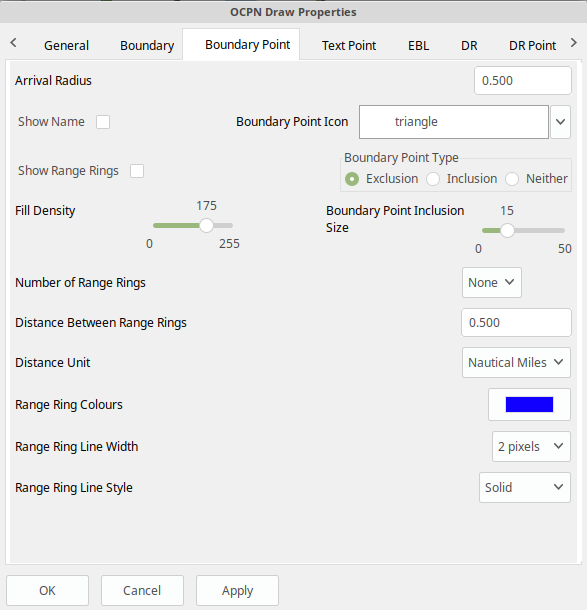
Arrival Radius
This is not really relevant to a Boundary Point at the moment, but may become useful if other items/capabilities are added
Show Name
This is the default setting for showing the Boundary Point name. Currently Boundary Points are created with the name empty/blank so nothing displays.
Icon
This is the default icon to use for all Boundary Points. There is a set of OpenCPN icons that can be used as well as user defined icons. The method of adding user defined icons is documented in the main OpenCPN manual
Show Range Rings
Boundary Points can have range rings associated with them. To show the rings by default this setting needs to be checked.
Boundary Point Type
This radio button selection sets the default type for all Boundary Points.
-
Exclusion - fill the inside range rings with a hash.
-
Inclusion - surround the largest range ring with a nominated size hash
-
Neither - just draw the range rings but there is no hash
Fill Density
This allows the setting of how transparent the fill hash is. A value of 0 means that it is fully transparent and a value of 255 is that it is fully opaque. The term density is used as it seemed clearer, i.e. low density - you can see through it, high density - you cannot see through it.
Boundary Point Inclusion Size
This defines, in pixels, how wide the hash is around the outside Boundary Point Range Ring when the Boundary Point is of type 'Inclusion'.
Number of Range Rings
This defines the number of range rings to show if they are selected to be shown. If Zero is selected, then there will be no range ring shown.
Distance Between Range Rings
This is the gap between sucessive range rings. The measurement this is using is defined in the Distance Unit' setting
Distance Unit
The unit of measurement to use for the range rings gap. It can be:
-
Nautical Miles
-
Kilometers
Range Ring colors
This is the default color to use for any Boundary Point Range Ring. When selected a standard, platform dependant, color picker will be presented. This will allow the color to be any RGB (Red, Green, Blue) color that is supported by the platform.
Range Ring Line Width
This is the width of the range rings when drawn in pixels. It can be a value between 1 and 10 pixels.
Range Ring Line Style
This defines how the Range Rings are drawn. It can be one of the following:
-
Solid
-
Dot
-
Long Dash
-
Short Dash
-
Dot Dash
Some of these may not display well on your screen depending on the resolution you are using. It is known that when using high resolution screens, i.e. 3800×1900 the difference between the line types may be difficult to see.
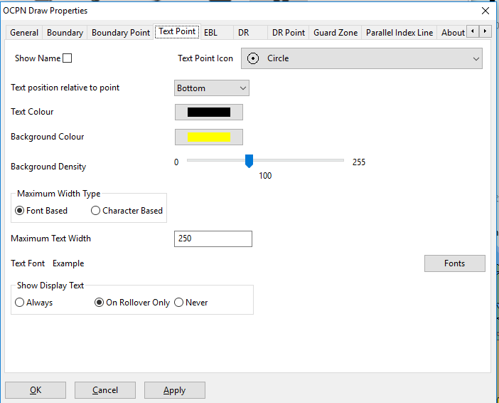
Text Point Icon
This is the default icon to use for all Text Points. There is a set of OpenCPN icons that can be used as well as user defined icons. The method of adding user defined icons is documented in the main OpenCPN manual.
Text Position
This selects where the text is positioned relative to the location of the Text Point. If you show an Icon it will be easier to see and interact with the text on the screen. If you do not use an Icon it may be easier to use the Path Manager to get to the Text Point.
There are 7 different locations:
-
Top
-
Top center
-
Bottom
-
Bottom center
-
center
-
Right
-
Left
Text color
This is the color that the default Display Text will have. Selection is by a platform specific color picker. This will allow the color to be any RGB (Red, Green, Blue) color that is supported by the platform.
Background color
When a Text Point displays text it will have a colored background to help it stand out from the underlying chart. This is the default color of the background box. This will allow the color to be any RGB (Red, Green, Blue) color that is supported by the platform.
Background Density
This allows the setting of how transparent the background color. A value of 0 means that it is fully transparent and a value of 255 is that it is fully opaque. The term density is used as it seemed clearer, i.e. low density–you can see through it, high density–you cannot see through it. The default density is 100.
Maximum Width Type
This selects either Font metric based sizing or Charcter count for wrapping the displayed text. In Font Based the font being used will determine where the wrapping occurs. In Character Based the count of the characters will determine where the wrapping occurs.
Show Display Text
This is the default for when the Display Text of a Text Point is shown.
-
Always - Display text is always shown
-
On Rollover Only - The text will be displayed when the mouse pointer rolls over the Text Point. This is to try and help declutter the screen if there are many objects being concurrently displayed.
-
Never - The display text is not displayed
Maximum Text Width
Depending on the selection of Maximum Width Type will determine the meaning of this number. In Font Based it is a virtual number more closely related to the number of pixels available to display the text. In Character Based this is the count of the maximum number of characters allowed on any line.
In Font Based the text will only be wrapped if there is a space in the text. Also, if the value is set too low there will be now wrapping of the text. To use this method you will need to tune your value dependent on the font being used. There is no relationship between this number and the number of characters that will be used on any particular line.
In Character Based this is the maximum number of characters that will be displayed on any line. Line breaks will occur on spaces, if they are available, but if there are no spaces then the line will be broken at this number of characters.
Text Font
This is the default font to be used for the 'Display Text'. The 'Fonts' button will allow picking of any font that is installed on the system. You can pick the Family, Style and Size of the font. This is presented by a platform specific font picker. The current font that will be used is shown by the work 'Example' which will be drawn using the font selected.
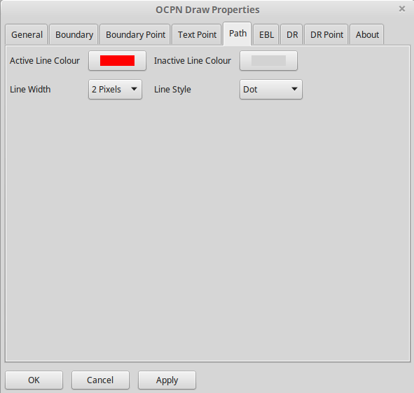
Active Line color
This is the color of an active generic Path if there is no specific type. Currently this is not used as there are no unspecified Path types in use. Selection is by a platform specific color picker. This will allow the color to be any RGB (Red, Green, Blue) color that is supported by the platform.
Inactive Line color
This is the color of an inactive generic Path if there is no specific type. Currently this is not used as there are no unspecified Path types in use. Selection is by a platform specific color picker. This will allow the color to be any RGB (Red, Green, Blue) color that is supported by the platform.
Line Style
This defines how the Path Line is drawn. It can be one of the following:
-
Solid
-
Dot
-
Long Dash
-
Short Dash
-
Dot Dash
Some of these may not display well on your screen depending on the resolution you are using. It is known that when using high resolution screens, i.e. 3800×1900 the difference between the line types may be difficult to see.
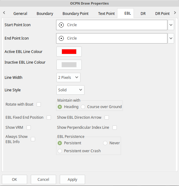
Start Point Icon
This is the default icon to use for the start point of an EBL. There is a set of OpenCPN icons that can be used as well as user defined icons. The method of adding user defined icons is documented in the main OpenCPN manual.
End Point Icon
This is the default icon to use for the end point of an EBL. There is a set of OpenCPN icons that can be used as well as user defined icons. The method of adding user defined icons is documented in the main OpenCPN manual.
Active EBL Line color
This is the color of an active EBL. Selection is by a platform specific color picker. This will allow the color to be any RGB (Red, Green, Blue) color that is supported by the platform.
Inactive EBL Line color
This is the color of an inactive EBL. Selection is by a platform specific color picker. This will allow the color to be any RGB (Red, Green, Blue) color that is supported by the platform.
Line Style
This defines how the EBL is drawn. It can be one of the following:
-
Solid
-
Dot
-
Long Dash
-
Short Dash
-
Dot Dash
EBL Fixed End Position
This the default for all EBLs. This fixes the End Point of an EBL such that when the boat moves the end point does not. If this is left uncheck the end point of the EBL will move with the boat so the EBL always has the same length and bearing.
Show EBL Direction Arrow
This is the default for all EBLs. If checked a direction arrow will be displayed on the EBL at or near the end point. This helps show the direction of the EBL.
Show VRM
This draws a Variable Range Marker (Ring) centered on the start point and sized to go through the end point.
Show Perpendicular Index Line
This shows a line drawn perpendicular to the end of the EBL. The line uses the same attributes as are applied to the EBL itself.
EBL Persistence
The EBLs that are created can be:
-
Persistent - will persist over a restart of OpenCPN
-
Persistent over Crash - will not persist over a normal restart of OpenCPN, but will be persistent over a crash of OpenCPN
-
Never - the EBL will only be temporary and will not be displayed again when OpenCPN is restarted.
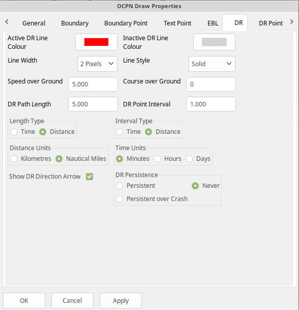
Active DR Line color
This is the color of an active DR Line Selection is by a platform specific color picker. This will allow the color to be any RGB (Red, Green, Blue) color that is supported by the platform.
Inactive DR Line color
This is the color of an inactive DR Line. Selection is by a platform specific color picker. This will allow the color to be any RGB (Red, Green, Blue) color that is supported by the platform.
Line Style
This defines how the DR line is drawn. It can be one of the following:
-
Solid
-
Dot
-
Long Dash
-
Short Dash
-
Dot Dash
Course over Ground
This is the default course over ground to use. The type, True or Magnetic, is determined by the setting in the General tab.
DR Persistence
The DR lines that are created can be:
-
Persistent - will persist over a restart of OpenCPN
-
Persistent over Crash - will not persist over a normal restart of OpenCPN, but will persist over a crash of OpenCPN
-
Never - the DR line will only be temporary and will not be displayed again when OpenCPN is restarted.
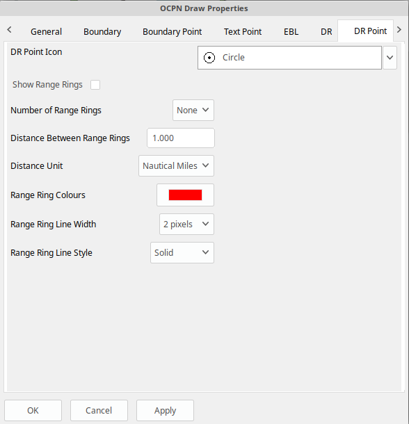
DR Point Icon
This is the default icon to use for the all points of a Dead Reckoning line. There is a set of OpenCPN icons that can be used as well as user defined icons. The method of adding user defined icons is documented in the main OpenCPN manual.
Show Range Rings
Boundary Points can have range rings associated with them. To show the rings by default this setting needs to be checked.
Number of Range Rings
This defines the number of range rings to show if they are selected to be shown. If Zero is selected, then there will be no range ring shown.
Distance Between Range Rings
This is the gap between successive range rings. The measurement this is using is defined in the 'Distance Unit' setting
Distance Unit
The unit of measurement to use for the range rings gap. It can be:
-
Nautical Miles
-
Kilometers
Range Ring colors
This is the default color to use for any DR Point Range Ring. When selected a standard, platform dependant, color picker will be presented. This will allow the color to be any RGB (Red, Green, Blue) color that is supported by the platform.
Range Ring Line Width
This is the width of the range rings when drawn in pixels. It can be a value between 1 and 10 pixels.
Range Ring Line Style
This defines how the Range Rings are drawn. It can be one of the following:
-
Solid
-
Dot
-
Long Dash
-
Short Dash
-
Dot Dash
Some of these may not display well on your screen depending on the resolution you are using. It is known that when using high resolution screens, i.e. 3800×1900 the difference between the line types may be difficult to see.
First Point Icon
This is the default icon to use for the first point placed when creating a Guard Zone (GZ). There is a set of OpenCPN icons that can be used as well as user defined icons.
The method of adding user defined icons is documented in the main OpenCPN manual.
Second Point Icon
This is the default icon to use for the second point placed when creating a Guard Zone (GZ). There is a set of OpenCPN icons that can be used as well as user defined icons. The method of adding user defined icons is documented in the main OpenCPN manual.
The method of adding user defined icons is documented in the main OpenCPN manual.
Active Line Color
This is the color of an active Boundary Line
Selection is by a platform specific color picker. This will allow the
color to be any RGB (Red, Green, Blue) color that is supported by the
platform.
Active Fill Color
This is the default color to use for any active Boundary fill hash. When selected a standard, platform dependent, color picker will be presented. This will allow the color to be any RGB (Red, Green, Blue) color that is supported by the platform.
Inactive Line Color
This is the color of an inactive Boundary Line.
Selection is by a platform specific color picker. This will allow the
color to be any RGB (Red, Green, Blue) color that is supported by the
platform.
Inactive Fill Color
This is the default color to use for any inactive Boundary fill hash. When selected a standard, platform dependent, color picker will be presented. This will allow the color to be any RGB (Red, Green, Blue) color that is supported by the platform.
Line Width
This is the width of the Boundary Line in pixels. It can be a value between 1 and 10 pixels.
Line Style
This defines how the Boundary Line is drawn. It can be one of the following:
-
Solid
-
Dot
-
Long Dash
-
Short Dash
-
Dot Dash
Some of these may not display well on your screen depending on the resolution you are using. It is known that when using high resolution screens, i.e. 3800×1900 the difference between the line types may be difficult to see.
Fill Density
This allows the setting of how transparent the fill hash is. A value of 0 means that it is fully transparent and a value of 255 is that it is fully opaque. The term density is used as it seemed clearer, i.e. low density - you can see through it, high density - you cannot see through it.
Rotate with Boat
This locks the GZ to either the heading the course over ground of the boat. If this is unset then the GZ will move with the boat but will be at a fixed direction from the boat irrespective of its course or heading.
Maintain with
This setting works with the 'Rotate with Boat' specifying whether to use the current heading or the course over ground.
This defines, in pixels, how wide the hash is around the outside Boundary Line when the Boundary is of type 'Inclusion'.
Guard Zone Persistence
The GZs that are created can be:
-
Persistent - will persist over a restart of OpenCPN
-
Persistent over Crash - will not persist over a normal restart of OpenCPN, but will be persistent over a crash of OpenCPN
-
Never - the GZ will only be temporary and will not be displayed again when OpenCPN is restarted.
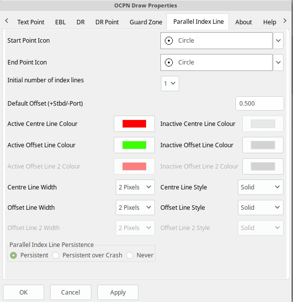
Start Point Icon
This is the default icon to use for the start point of an PIL. There is a set of OpenCPN icons that can be used as well as user defined icons. The method of adding user defined icons is documented in the main OpenCPN manual.
End Point Icon
This is the default icon to use for the end point of an PIL. There is a set of OpenCPN icons that can be used as well as user defined icons. The method of adding user defined icons is documented in the main OpenCPN manual.
Active Centre Line color
This is the color of an active PIL centre line. Selection is by a platform specific color picker. This will allow the color to be any RGB (Red, Green, Blue) color that is supported by the platform.
Inactive Centre Line color
This is the color of an inactive PIL centre line. Selection is by a platform specific color picker. This will allow the color to be any RGB (Red, Green, Blue) color that is supported by the platform.
Active Offset Line color
This is the color of an active PIL offset line. Selection is by a platform specific color picker. This will allow the color to be any RGB (Red, Green, Blue) color that is supported by the platform.
Inactive Offset Line color
This is the color of an inactive PIL offset line. Selection is by a platform specific color picker. This will allow the color to be any RGB (Red, Green, Blue) color that is supported by the platform.
Centre Line Width
This is the width of the PIL centre line in pixels. It can be a value between 1 and 10 pixels.
Centre Line Style
This defines how the PIL centre line is drawn. It can be one of the following:
-
Solid
-
Dot
-
Long Dash
-
Short Dash
-
Dot Dash
Offset Line Width
This is the width of the PIL offset line in pixels. It can be a value between 1 and 10 pixels.
Offset Line Style
This defines how the PIL offset line is drawn. It can be one of the following:
-
Solid
-
Dot
-
Long Dash
-
Short Dash
-
Dot Dash
Line Style
This defines how the EBL is drawn. It can be one of the following:
-
Solid
-
Dot
-
Long Dash
-
Short Dash
Dot Dash
Parallel Index Line Persistence
The EPILs that are created can be:
-
Persistent - will persist over a restart of OpenCPN
-
Persistent over Crash - will not persist over a normal restart of OpenCPN, but will be persistent over a crash of OpenCPN
-
Never - the PIL will only be temporary and will not be displayed again when OpenCPN is restarted.
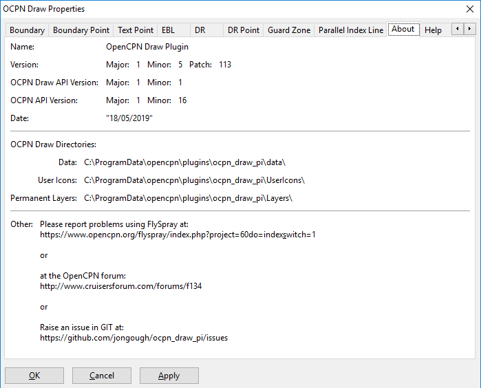
OCPN_Draw directories
OCPN_Draw uses a set of directories to hold information and data, these directories are within the OpenCPN directory structure but linked to this plugin. The directories which are used are platform and installation dependent, however, the location can be found in the 'OCPN Draw Properties' dialog under the 'About' tab. This dialog is accessible from the 'OpenCPN Options', 'Plugins' dialog page. This will show the location of the 'data' sub-directory where the ODnavobj.xml files are kept. The other directories are siblings of the data directory and are 'Layers' and 'UserIcons', which hold data related to their names.
Possible Future Improvements:
Match
It might be nice to have a way to “match” a text entity which is a way
of copying all the font, color, background color and transparency
information. To clone the properties of an object and not necessarily
the object itself. So, the idea is to copy some of the attributes,
colour, text, icon from one point to another, but leaving the lat, lon,
GUID, name? remember the “the change all icons for boundaries” you have
implemented already.
Croatia Anchorages Script
Jobe39 has created a Simple Python File to convert gpx file from http://www.anchoragesincroatia.net/p/map-download.html for the OpenCPN draw plugin.
Also see Feature Request - Import GPX files for anchorages in croatia #386 for information about the process.
Why can’t EBL lat/long be copied or changed?
The EBL is really defined as a length and direction from a starting point, the default being the boat. The ODPoints that are used are to enable moving the end points to a user selected location, which really translates into a length and direction. If you fix the end point, i.e. it does not move with the boat (a check box is available for this in the properties) then the end point lat/lon is stable and does not change, this allows the user to then input the lat/lon they wish. If they then allow the end point to move, uncheck the check box, it will use the new lat/lon as the starting point for the EBL.
Copying the lat/lon of a moving point would probably not give you the answer you were hoping for. As the end point changes as the boat moves and rotates, the real life probability of getting the lat/lon you thought you would is unlikely. The way of showing that the lat/lon is changing is by making these fields read only, i.e. you cannot interact with them in any way, so there is no way to get the event for copying them. This is a restriction on the current implementation of wxWidgets.